| Item |
Specifications |
| Input
voltage class |
3-phase 200V
input/3-phase 400V input/1-phase 200V input |
| Applicable
motor capacity (kW) |
0.2 |
0.4 |
0.75 |
1.5 |
2.2 |
3.7 |
5.5 |
7.5 |
11 |
15 |
| Type |
Input voltage class |
Model |
VFS7/VFD7/VFS7s |
| 3-phase 200V class |
VFS7- |
|
2004P |
2007P |
2015P |
2022P |
2037P |
2055P |
2075P |
2110P |
2150P |
| 3-phase 400V class |
VFS7- |
|
|
|
4015P |
4022P |
4037P |
4055P |
4075P |
4411P |
4150P |
| 1-phase 400V class |
VF37S- |
2002P |
2004P |
2007P |
2015P |
|
|
|
|
|
|
| Rating |
Capacity |
0.6 |
1.2 |
1.6 |
3.0 |
4.0 |
6.5 |
9.5 |
13 |
19 |
25 |
| Rated
output current (A) |
3-phase 200V class |
|
3.0 |
4.0 |
7.5 |
10.0 |
16.5 |
25 |
33 |
49 |
66 |
| 3-phase 400V class |
|
|
|
4.0 |
5.0 |
8.5 |
13 |
17 |
25 |
33 |
| 1-phase 200V class |
1.5 |
3.0 |
4.0 |
7.5 |
|
|
|
|
|
|
| Power
supply |
Voltage
& frequency |
3-PHASE 200-220v-50Hz,
200V-50Hz/3-phase 380-460V-60Hz/1-phase 200-220V-50Hz, 200-230V-60Hz |
| Tolerance |
Voltage:
±10%, Frequency: ±5% |
| Main
control functions |
Control
method |
Sinusdal
PWM control |
| Rated
output voltage |
The voltage
is controlled to within 100-120% of the rated voltage (200/400V) by the power
supply voltage compensating function (output voltage cannot exceed input voltage). |
| Output
frequency range |
0.5-320Hz,
set to 0.5-60Hz be default, maximum frequency adjustment (30-320Hz) |
| Frequency
setting resolution |
0.1Hz; input
from operator panel, 0.2Hz; Analog input ( at the maximum frequency of 100Hz) |
| Frequency
accuracy |
Digital setting:
±0.01% of the max. output frequency or less (at -10-±50°C),
Analog setting: ±0.5% of the max. output frequency or less (at 25±10°C) |
| Voltage/frequency
characteristics |
V/f constant
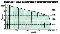
mode, square reduction mode, sensorless vector control mode, automatic torque
boost mode, energy-saving mode, base frequency (25-320Hz) adjustment, torque boost
(0-30%) adjustment |
| Overload
current rating |
60 seconds
at 150% |
| Frequency
setting signal |
Built-in
potentiometer; External potentiometer (1-10kR potentiometer connection); 0-10
Vdc (input impedence: VIA=30.55 kR/VIB=30kR); 4-20mAdc (input impedence: 400R);
control characteristics (gain, bias) can be set by a 2-point setting. |
| Operation
specifications |
Start
frequency, frequency jump |
Adjustable
from 0-10Hz/jump frequency and band settings can be set three points. |
| PWM
carrier frequency |
Adjustable
between 2.2 and 12kHz (default value: 12kHz) |
| Acceleration/decelaration
time |
0.1-3600
seconds, acceleration/deceleration time #1 and #2 selection, acceleration/deceleration
pattern selection |
| Retry |
When a protective
function activates, after main circuit devices are checked, running restarts.
Settable to a max of 10 times |
| Dynamic
braking |
1-phase 200V/3-phase
200V class |
N/A |
Incorporates
a dynamic brake drive circuit with external braking resistor (optional). |
| 3-phase 400V class |
- |
Incorporates
a dynamic brake drive circuit with external braking resistor (optional). |
|
DC
injection braking |
Braking start
frequency adjustment (0-maximum frequency), braking current adjustment (1-100%),
braking time adjustment (0-20 seconds) |
|
Input
terminal function (selection) |
Forward/reverse
rotation input signal, jog operation input signal, operation preparation input
signal, preset speeds operation input (up to 15 preset speed operation), emergency
stop input signal, etc. |
|
Output
terminal function |
Lower limit
frequency output signal, upper limit frequency output signal, low speed output
signal, speed reached output signal, speed reach output signal, etc. |
|
Failure
detection signal |
1c contact
output (230 Vac-0.3 A-cosØ=4) |
|
Frequency
meter, ammeter |
Analog output
(1mAdc full scale DC ammeter, or 7.5 Vdc full scale voltmeter, current maximum-1mAdc,
7.5 Vdc, full scale) |
| Protective
specifications |
Protective
function |
Stall prevention,
current limit, overcurrent, output-side short circuit, overvoltage restriction,
undervoltage, overvoltage restriction, undervoltage, electronic thermal overload,
armature overcurrent during start up, load-side overcurrent during start up, emergency
stop (optional) |
| Counter
measures against instantaneous power failure |
Auto-restart
and regeneration power ride-through control |
|
Electronic
thermal protection characterisitics |
Switching
between standard motor and constant-torque VF motor, and selecting overload trip,
or overload stall |
| Display
specifications |
4-digit,
7-segment LED |
Frequency
display: Inverter output frequency: Inverter output frequency |
| Alarm display:
In-operation stall alarm "C", overvoltage limit alarm "P", overload alarm "L" |
| Status display:
Inverter status (setting frequency, cause of trip, input/output voltage, output
current, etc) and setting parameters |
| Free unit
display: Arbitary-unit display for output frequency |
| Discrete
LEDs |
Displays
inverter status with RUN lamp, MON lamp, PRG lamp, VEC lamp, ECN lamp, POTENTIOMETER |
| Service
conditions |
Service
environment |
Indoor, 1000m
or less, not subject to direct sunlight or corrosive/explosive gases; vibration:
5.9m/S² (0.6G) or less, (20-50Hz) |
| Ambient
temperature/relative humidity |
-10-140°C
(Max. 50°C possible when the top seal is removed)/85% (no condensation allowed) |
| Protective
structure/cooling structure |
Sealed structure/self-cooled |
Sealed structuer/forced
air-cooled |


